Audio enhancement perma-grin style
Results 1 to 10 of 153

Thread: Audio enhancement perma-grin style

Hybrid View

Previous Post Previous Post   Next Post Next Post
  1. #1
    Senior Member F6Pilot's Avatar
    Join Date
    May 2014
    Location
    Chattanooga, TN
    Posts
    418
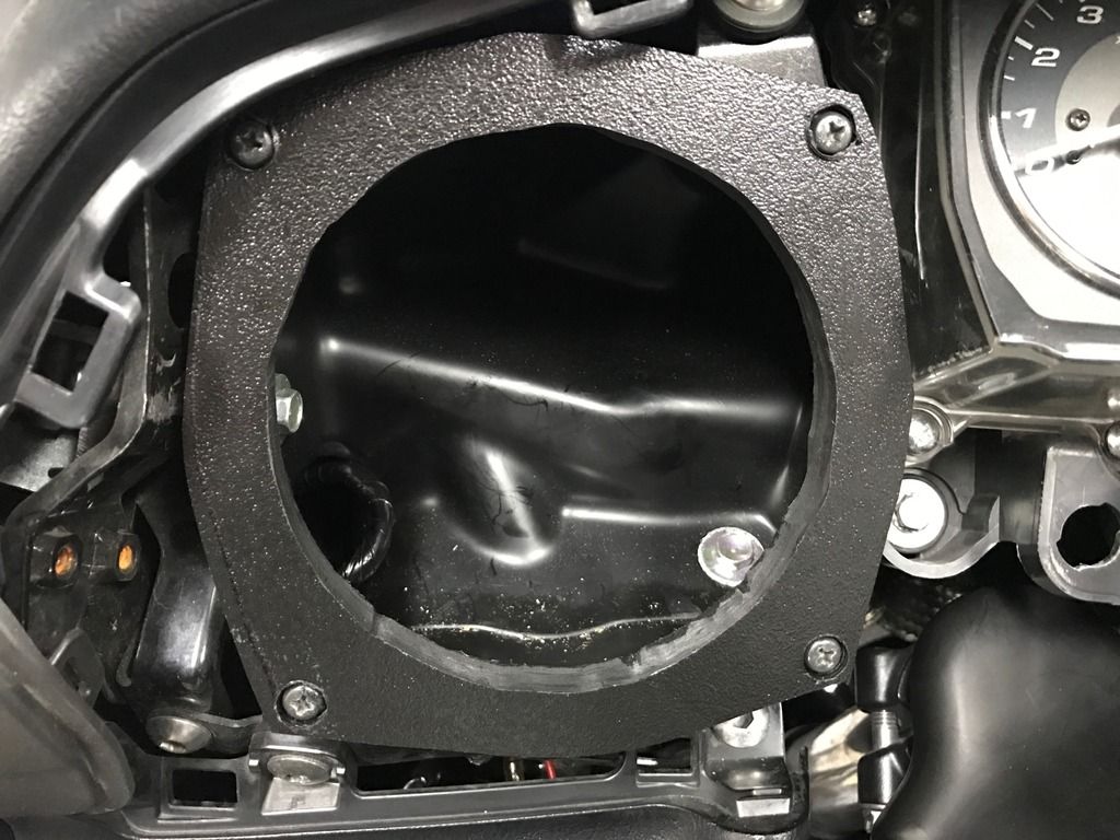
    While I await resolution for the tweeter issue, I decided to go ahead and work on the mids. I cut some spacers from 1/2" HDPE and utilized the stock speaker screws to mount the spacers to the dash.

    Attachment 24947 Attachment 24948 Attachment 24949 Attachment 24950

    Tomorrow I will start running a pair of 14/4 wires from the speakers back to the amp.

  2. #2
    Senior Member CoCoKola's Avatar
    Join Date
    Jun 2013
    Posts
    290
    Quote Originally Posted by F6Pilot View Post
    While I await resolution for the tweeter issue, I decided to go ahead and work on the mids. I cut some spacers from 1/2" HDPE and utilized the stock speaker screws to mount the spacers to the dash.


    Tomorrow I will start running a pair of 14/4 wires from the speakers back to the amp.
    It's been a really tough year, and this month has been the straw breaking the camel's back. I've not had much time to document/follow along, but there is light at the end of the tunnel. I would take a meter and touch anything/everything that MIGHT be a connection point and measure resistance. I'm betting you can find where those leads were connected...

    I'm pleased to see you are making progress, and I look forward to hearing your opinion. Frankly, the Audison really makes the difference between good and great. It seems if you don't mind warranty possibly being a challenge, you can buy the 8.9 Audison for 1/2 what I paid for it.

    Earlier, I mentioned the Audison has a de-EQ that allows it to compensate for any "EQ"ing that the head unit does to the output. It's pretty simple, you play an included CD through your head unit, and it measures each channel against an expected output level for each frequency. It builds a curve that is inserted at the beginning of the processing chain. You set bass/treble to 0, turn off the bass boost, volume compensation etc for the test. I used the AUX input connected to a CD player.

    Here is what it showed. Notice everything below 100Hz is dumped, the "bass boost" where the stock can push some low end between 100Hz and 500Hz, the strange boost about 1k, and the highs that seem to roll off. This should be as close to a straight line between the left and right sides of the measurement.

    Attachment 24966

    More to come..

  3. #3
    Senior Member F6Pilot's Avatar
    Join Date
    May 2014
    Location
    Chattanooga, TN
    Posts
    418
    With further inspection of the tweeters under a magnifying glass, I simply could not identify a connection point. I assume the connections ran up through a pair of those holes but I can't confirm without completing dismantling the casing. I ended up locating some more HT25 components which arrived today.

    Now I must decide if I try to pull the grill off of another tweeter, potentially creating the same disastrous/expensive result, or simply cut holes in the factory mesh grills and surface mount.

    I additionally pulled the front end apart and got the wiring routed from the crossovers to the speaker pods. I mounted the crossovers to another slab of HDPE and plan to secure them under the right cubby cover.

    Attachment 24969Attachment 24970Attachment 24972

  4. #4
    Senior Member CoCoKola's Avatar
    Join Date
    Jun 2013
    Posts
    290
    Quote Originally Posted by F6Pilot View Post
    With further inspection of the tweeters under a magnifying glass, I simply could not identify a connection point. I assume the connections ran up through a pair of those holes but I can't confirm without completing dismantling the casing. I ended up locating some more HT25 components which arrived today.

    Now I must decide if I try to pull the grill off of another tweeter, potentially creating the same disastrous/expensive result, or simply cut holes in the factory mesh grills and surface mount.

    I additionally pulled the front end apart and got the wiring routed from the crossovers to the speaker pods. I mounted the crossovers to another slab of HDPE and plan to secure them under the right cubby cover.
    That was the approach I took. It seemed cheaper to source a replacement cover than mess with the tweeters. I was concerned about affecting the output as well. In any case, it sounds like you are getting close to getting this wrapped up!

    One item I also added was the boom mat to help seal the compartment. I ordered both the 5.25 and 6.5 - the 6.5 had enough room for the magnet and an A/B comparison did seem improved / less resonance / tighter bass.

    Cheers!

  5. #5
    Senior Member F6Pilot's Avatar
    Join Date
    May 2014
    Location
    Chattanooga, TN
    Posts
    418
    Great tip, I will get some boom mats ordered as well. Tonight I pulled the back end apart and got wires routed from the crossover cubby back to the left saddlebag where the amp resides.


    Attachment 24973Attachment 24974

    Now I also get to do a lot of reading to determine how I connect the amp to the speakers and then how/where I pull signal from the factory head unit. Fun....

  6. #6
    Senior Member willtill's Avatar
    Join Date
    Aug 2015
    Location
    Maryland
    Posts
    4,622
    Jeff, can you post larger pictures? Am interested in the pictorial details of your install... but the thumbnails are not adequate for viewing such.


    21 years Army (retired)
    ...been everywhere, seen everything, done almost everything.

    IBA 80537

  7. #7
    Senior Member F6Pilot's Avatar
    Join Date
    May 2014
    Location
    Chattanooga, TN
    Posts
    418
    Will, I couldn't edit the original posts so let me know if these are any better. The site keeps downsizing the files to around 20k.

    Attachment 24976Attachment 24975

  8. #8
    Senior Member CoCoKola's Avatar
    Join Date
    Jun 2013
    Posts
    290
    Quote Originally Posted by F6Pilot View Post
    Great tip, I will get some boom mats ordered as well. Tonight I pulled the back end apart and got wires routed from the crossover cubby back to the left saddlebag where the amp resides.


    Attachment 24973Attachment 24974

    Now I also get to do a lot of reading to determine how I connect the amp to the speakers and then how/where I pull signal from the factory head unit. Fun....
    I used posilocks or positaps (depending on your preference.) Make sure you get the 20-22 gauge for the audio in -> your RCA cable (twisted type only!) used with shrink-wrap for each cable PLUS a 1.5-2" shrink-wrap to bundle the entire set of cables. Seems the best way to ensure a water-proof and vibration-proof connection.


    The service manual has the wiring diagram in the back, you just tap off the head unit where it connects to the factory amp. I just cut each cable (Brown is battery positive switched I believe, so be careful of the two 20 amp circuits!) and used the posilocks for the 8 connections and I pulled the stock amplifier to reduce the pull on the battery - reduce weight. You could use just the front, but I wanted the rear to use as input to the subwoofer, and you can use the fader to balance fronts from the rear. With the Audison, it has its own controller, so it is maybe less important.

    Also, note that I used the switched power from these Brown wires for the ACC on for my Audison. I would not do it this way again and instead use the acc taps from the battery accessory terminal.

    EDITED: added additional info and corrected spelling errors.

  9. #9
    Senior Member F6Pilot's Avatar
    Join Date
    May 2014
    Location
    Chattanooga, TN
    Posts
    418
    Let's give this a try...


Posting Permissions

  • You may not post new threads
  • You may not post replies
  • You may not post attachments
  • You may not edit your posts
  •