Well, I guess those are big enough. Will, let me know which additional images you would like to see and I will get them loaded for you.

Jeff, that is perfect! Thanks a lot.Originally Posted by F6Pilot

I had copied your thumbnails previously and zoomed in on them... but the resolution was too grainy
If you can upload the disassembled fairing as well...
I would need to put the crossovers somewhere else... since I have the cruise control module installed in the right fairing pocket.
I know others on the site are appreciating the larger images too! It gives more detail
21 years Army (retired)
...been everywhere, seen everything, done almost everything.
IBA 80537
No problem Will, I just had to learn the process on Photobucket. The forum software bumps the images down to 20k.
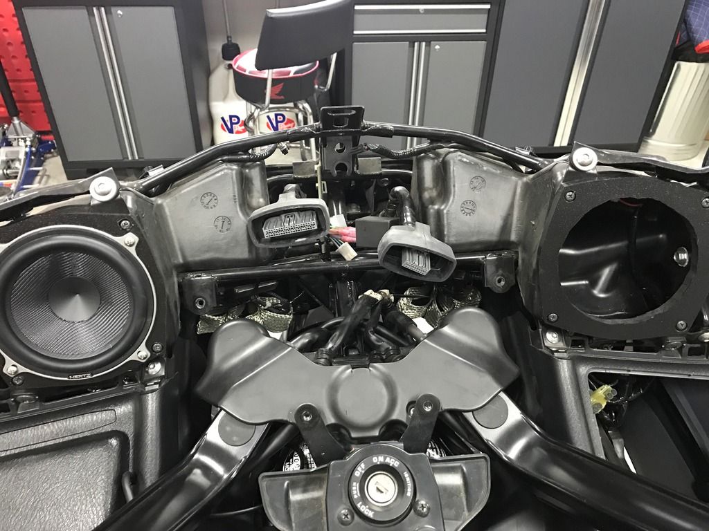
The crossovers are quite large which makes placement difficult. They will fit in the fairing behind the gauges but it will be tight and somewhat difficult to ensure they are secured appropriately. I also was concerned with how open the fairing was and the potential for grime and debris.

Jeff - thanks! I'm doing this mod soon. Shopping for the HSK 130s right now.
Cheers,
Steve
My girls:
Isleen - 2014 F6BD
Saorla - 1995 FLSTN Heritage Special
"Politeness, n: The most acceptable hypocrisy."
Ambrose Bierce
Here is my start on the wiring. I will readily admit to being a novice, tilting more to the mechanical side than the electrical. You know, if you cant fix it with a bigger hammer...you've got an electrical problem.
I have posilocks on the way to help with the interconnects, but will really need some help understanding the "from" stock wiring and "to" where on the amp. Based on Robert's earlier comments, I assume I'm tapping two inputs going into the factory amp and connecting those to the RCA jacks. I further assume there is also a trigger wire for the "turn on" lug on the Arc amp. I have the FSM and will start trying to identify the appropriate wires this weekend.

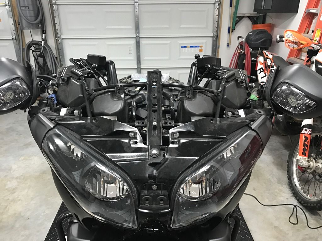
I believe I mentioned this before, but I ended up installing the X-overs in an unused space in front. It requires you to remove the windshield and the front fairing. In between the headlights is a space that the x-overs fit vertically - one on each side. This is an old photo when I was still testing the Polks, but the x-over fits nicely here.
Attachment 24987
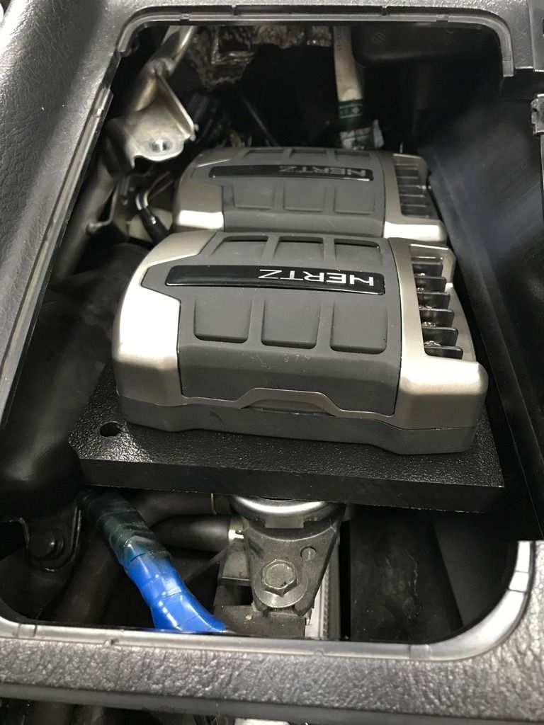
Here is a photo during a test fitting, prior to placement of the tweeters, as well as a photo showing the mats installed. I will take the bike apart to get photos of the final install. I remember now, I was pushing to get everything installed prior to the rally & bike week. Attachment 2498920160903_162032-01.jpg
F6Pilot: I am the polar <cough> opposite. Completing this audio upgrade was my trial by fire as a mechanic. Electrons are my friends. The fabrication was truly an adventure in "oh $hit, now what" but thanks to several here, I made it to the finish line.
The short <cough> answer is the accessory power pull from the accessory power tab to the left of the battery (I will double check that this is OFF during starter press.) I used the accessory power the stock amp used, but twice during my initial setup, when I had the bike in ACC mode for a while during start depress the sub amp didn't mute and it passed a not so nice signal. I believe this can be fixed by a config change on the 8.9 amp configuration, your post reminded me to verify the cause and resolve it.
Here is the wiring diagram for the input Molex for the Audison 8.9 and includes the F6B wiring colors and purpose. This chart should work with the ARC or other amps to know what to map to your amp's input side.
Audison Molex
Purpose
F6B Wire 16 White Front Left + Yellow/Black 8 White/Blk Front Left Green/Black 15 Gray Front Right + Red/Black 7 Gray/Blk Front Right Black/White* 14 Green Rear Left + Pink 6 Green/Blk Rear left Light Green 13 Violet Rear Right + Blue/Black 5 violet/Blk Rear Right White/Back*
For those who have a shop manual, and for your reference, codes used are the following for the F6B:
Bl Black
BR Brown
Bu Blue
G Green
Gr- Gray
Lb Light Blue
Lg Light Green
O Orange
P Pink
Pu Purple
R Red
W White
Y Yellow
Attachment 24991 Attachment 24992
That should get you going. Hope this info helps, it was a $itch to put together
Robert, thank you for the detailed information. It will speed up my discovery process immensely. There is one piece I am thoroughly confused on and that is the conversion from the pre-amp wires to RCA connectors. I am only running front components so per the manual there are essentially only four wires coming from the head unit into the amp. They feed both the tweeters and the mids and I should tap in to these lines prior to the factory amp. I'm assuming an RCA is essentially a ring and tip configuration for + and - so do you use a high/low convertor to convert from basic wires to the RCA? Additionally, what determines whether the tip or ring is + or -?
 Posting Permissions


 Reply With Quote